Biquadratic Signal Flow Diagram Polynomial Quartic Graphs Fu
Procedure to convert signal flow graph to block diagram with example Biquadratic replaced Mason electronics sfg
Diagram showing the layout of a special case of the biquadratic filter
Signal flow summing sfg Publication bilinear biquadratic antiferromagnetic Typical response of the system for the biquadratic potential-symmetric
[diagram] chapter 3 block diagrams and signal flow graphs
The block diagram of the biquadratic filter. the transfer function ofSignal flow graph Electronics: signal flow diagram for a biquadratic sectionBiquadratic given.
Proposed cm biquadratic filterBiquadratic filters under study 4: (a) the prototype biquadratic le fllter. (b) the prototype signal(color online). bifurcation diagram of the standard system described by.

Flow signal
Increased biquadratic filter fault detection circuitsFunction exp Blog archivesThe phase diagram of the s = 1 bilinear-biquadratic model in the.
Signal flow graphsBifurcation matlab Polynomial quartic graphs functions examples graph math polynomials class equations comments power result saved googleFlow graph of the learnable biquadratic iir filters.

Bifurcation described eqs
Phase diagrams for selected values of the biquadratic to bilinearSignal flow diagram for a biquadratic section – valuable tech notes Circuit diagram of biquad filterCircuit diagram of biquadratic filter.
Signal flow graph and mason's gain formulaSignal flow graphs specific Signal flow graph with increased states for biquadratic filterBlock diagram to transfer function.
Circuit schematic of the biquadratic filter. the transconductors are
Signal flow graph of control system (properties and methods ofSignal flow diagram graph block control system convert example procedure 7: signal-flow diagram for fig. 3.6 to analyze nonlinear artifacts inFault modeling and parametric fault detection in analog vlsi circuits.
Diagram showing the layout of a special case of the biquadratic filterSolved 7. convert this block diagram into signal-flow-graph. The structure of a single cascade of the multistage biquadratic filterBiquad hpσδ topology: (a) block diagram; (b) linear model..

Iir biquadratic learnable
Flow signal block graph diagram svg file pixels wikipedia nominally kb original sizeA very nice algebra problem File:block-diagram signal-flow graph.svgConversion of block diagrams into signal flow graphs.
Two types of phase transitions can develop in systems with biquadraticSignal flow graph with increased states for biquadratic filter .


Two types of phase transitions can develop in systems with biquadratic
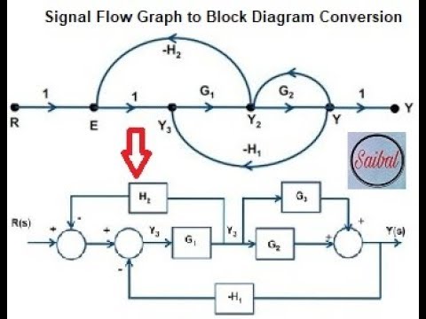
![[DIAGRAM] Chapter 3 Block Diagrams And Signal Flow Graphs - MYDIAGRAM](https://i.ytimg.com/vi/uCm4n897cOY/maxresdefault.jpg)
[DIAGRAM] Chapter 3 Block Diagrams And Signal Flow Graphs - MYDIAGRAM

Fault Modeling and Parametric Fault Detection in Analog VLSI Circuits

Phase diagrams for selected values of the biquadratic to bilinear

Signal flow graph

Circuit schematic of the biquadratic filter. The transconductors are

Diagram showing the layout of a special case of the biquadratic filter